DC Protection / Time Delay for Loudspeaker
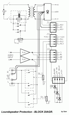
A exceptionally useful circuit for all the final amplifiers, but also in other applications that we needed some time delay and protection DC. The particular circuit combines enough operations, as: [ 1 ] Smooth departure of benefit of AC line of network, with delay 1sec, to the transformers of power supply of amplifier, via the RL1 and the resistance Rx. (see block diagram). [ 2 ] Delay of connection of expenses of final amplifiers, in headphone, in order that noises emanating from the charge - uncharged of capacitors of power supply, they do not pass in them. Simultaneously becomes control of exit of amplifiers for existence of continuous voltage [DC]. If all go well it connects, the amplifiers in loudspeaker. At the duration of operation of amplifiers, exists continuous control, for DC voltage in the exit of amplifiers, unplug him loudspeaker, if is presented problem ph. "opens" some transistor in the final stage and passes the voltage of supply to loudspeaker. [ 3 ] Clue of situation ERROR, optically with the LD3 (can is flash led) and soundly with buzzer (BZ). [ 4 ]. A other operation that exists and with difficulty will find in proportional circuits, is also the existence second relay (RL3), with parallel contacts in the main relay (RL2), connection the loudspeaker in the amplifiers, that it little closes afterwards the RL2. The idea I add one still relay, was supported in the problems that exist, after frequent use of RL2, his contacts are degraded by the electric arcs that are created when it opens and closes relay. Result is a spectrum of frequencies, because the high resistance that is developed in the contacts, the sound of be degraded. This problem is untied to a large extent, if are added, other contacts at the same time with first, that would close after them, remaining thus clean, one and are not created, on them, differences of potential, so that they are degraded. The circuit can work excellently also in actively loudspeaker one and the circuits of detection DC, afterwards the J2, can make so much all loudspeakers we have. In this case, they will need so much circuits of protection, that actively loudspeaker, we have. In the BLOCK diagram I give a flavour of typical connections, that can become, when the circuit use in stereo amplifier and his supply are taken from main power supply his.How it works
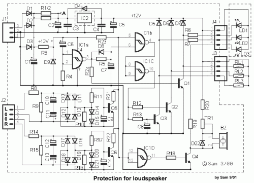
The supply of circuit becomes from a AC line in the J1. This voltage can be from a separate transformer 2X12V (the prices of materials that I give it is for 2X12V AC), from existing coil 12V in their M/T of power amplifier or if it cannot become somebody from the two, then from the coils of mainly supply final amplifier, adapting always the prices of resistances R1/2 and R3, proportionally the price of voltage that is supplied the amplifier, according to the law of Ohm and the fall of voltage that we want to achieve (R=V/i). The voltage that it should we have in point A, before the IC2, should is bigger than + 15V 200mA, the IC2 supplies all the relay and led. The remainder circuit is supplied by the R3/D9. When we supply the amplifier with voltage of network (220V AC), charge the C6 via the R4, the price in the entry of IC1a is (H) exit (L) Q1- RL1, is in cutting off. In line with being first the M/T of power supply, intervenes the RX, which ensures smooth connection the M/T in the network, avoiding the burn of fuses, specifically if the force power supply, is big. After 1sec after charge the C6, his negative pole goes to 0V, the entry of IC1A becomes 0V (L), conduct Q1 closes the RL1, short the resistance RX and all the voltage of network is applied in the M/T. Simultaneously turns on LD 1. Via the R5 charge slow the C7 (~5sec), when charge the situation in the pin5 of IC1b become (H), (the other are already (H) from the R23), exit is (L) and the exit of IC1C (H), the Q2 drive the RL2, giving the output of amplifiers in loudspeaker. Simultaneously via the R13 charge the C8 (~2 sec). Hardly charge the C8, conduct the Q3 and close the contacts of RL3, at the same time with those of RL2. The circuit is in complete operation. If we interrupt the line of network all the supply’s fall very fast, with result all relay is cut off, very rapidly cut off, him loudspeakers. If are presented some continuous voltage in entries J2/1 and J2/4, the two circuits of detection DC, then the Q5 or Q6 conduct and lead the entry of IC1b to pin 5 to 0V (L), with result the exit is become (H), the exit of IC1c to be become (L), transistors Q2-3 are cut off and away also the RL2-3 to open, disconnect, him loudspeakers, from the output of amplifiers, until is raised the cause of presence DC.. The same time the exit of IC1D, becomes (H), Q4 conduct, the buzzer [BZ] sounds and turns on the LD3, signaling error. The intensity of sound of BZ, can be regulated from the TR1, but it can it is suppressed if we do not want sound clue of error. The prices of times can change, if are changed capacitors C7-8, with different capacity. Resistances R1-2 if use finally, R3 and RΧ, should be in some distance from pcb, one and likely hot. The IC2 should enter on heatsink, specifically if the voltage of entry exceeds the +15V. Big attention it should we give in the circuit round resistance RX/CX and the contacts of RL1, because the voltage of network is dangerous (DANGER of ELECTROCUTION). For this reason good it is insulation. What it should we are careful is the quality of all relay, is very good and from known constructor.Circuit diagram
Part list
- R1-2=See text*
- R3=470R 1W*see text
- R4-5= 1M
- R6-7= 1K
- R8-14= 15K
- R9-15= 56K
- R10-16= 56K
- R11-17= 10K
- R12-13= 39K
- R18= 39K
- R19= 1K2
- R20= 1K
- R21-22= 3K9
- R23= 22K
- R24= 39K
- RX= 47R 10W
- C1= 220uF 63V
- C2-5= 47uF 63V
- C3-4=100nF
- C6= 1uF 25V
- C7= 4.7uF 25V
- C8= 470uF 16V
- C9-14= 22uF 16V
- C10-13= 33uF 63V
- CX= 33nF 630V
- IC1= 4093 cmos
- IC2= 7812T
- Q1-4= BD679
- Q5-6= BC550C
- D1-4= 1N4007
- D5-8= 1N4148
- D9=12V 1.2W Zener
- D10-22= 1N4148
- LD1-2= LED
- LD3=Flash Led [RED]
- BZ= BUZZER 12V
- J1-4= Connectors
- TR1= 10K Trimmer
- RL1-3= 12V 2X2(10A)RELAY


