Followers

Showing posts with label Equalizer. Show all posts

10 Band Graphic Equalizer

Download sekema equalizer :

10 Band Graphic Equalizer
     

       With graphic equalizer we make selective cutting off or boost, of selected departments of acoustic spectrum. With this way we can adapt the musical reproduction, in the characteristics of space where we hear. This can create however also problems if go to far specifically in the gain of some area, with result the distortion. The circuit should be made in two pieces, one for each channel, the potesometer regulation it should they are Fader. With switch S1 we can by pass the circuit, leaving the musical program, to pass without alteration (FLAT). With the potesometer RV1 we regulate the gain of each channel.

ΤΕΧΝΙΚΑ ΧΑΡΑΚΤΗΡΙΣΤΙΚΑ ΠΡΟΤΥΠΟΥ - PROTYPE SPECIFICATIONS

Απόκριση συχνότητας - Frequency Response 10ΗΖ - 30 ΚΗΖ ±0.5db
Ρύθμιση κέρδους κάθε περιοχής - Adjust Gain for eatch band ±12 dB
Ρύθμιση κέρδους - Adjust Gain for eatch Channel - 9db to +14db
S/N 82db
Παραμόρφωση (FLAT) - T.H.D 0.03%
Σύνθετη αντίσταση εισόδου - Input Impedance 47ΚΩ
Σύνθετη αντίσταση εξόδου - Output  Impedance 100Ω
Τροφοδοσία - Power Supply ±15V dc / 300 mA

Part List

R1-29=100 ohms C7=220nF 100V C20=1nF 100V
R2-5-31=1Mohms C8=100nF 100V C21=560pF
R3=47Kohms C9=47nF 100V C22=270pF
R4=15Kohms C10=27nF 100V C23=150pF
R6-28=10Kohms C11=12nF 100V C25=150pF
R7....17=1Kohms C12=6.8nF 100V C26=10uF/25V
R18....27=220Kohms C13=3.3nF 100V RV1=250Kohms Lin.
C1=47uF/25V C14=68nF 100V RV2.....12=4.7Kohms Lin.
C2=47pF C15=33nF 100V IC1...3=TL074
C3=150pF C16=18nF 100V S1=2X2 SW
C4=1.5uF 100V C17=8.2nF 100V J1...3=RCA Jack
C5=820nF 100V C18=3.9nF 100V All Resitors is 1/4W 1%
C6=390nF 100V C19=2.2nF 100V

6-Band Graphic Equalizer


 Download skema Equalizer

6 Band Graphic Equalizer


   The EQ-2 it is a circuit of graphic equalizer 6 band of regulation. Each band is regulated from the potesometers RV1-6, that are, for better optical indicate of regulations, Fader. This does not mean that we cannot him replace with simply potesometer. In the center of regulation potesometer, the gain is null (flat), but in terminal has +/- 15 db, boost or cutting off, respectively. For stereo operation, it will be supposed two times.

Part List

R1=47Kohms C2=15nF 100V C9=680nF 100V
R2-5-18=150Kohms C3=150nF 100V C10=150nF 100V
R3-4=10Kohms C4=33nF 100V C11=39nF 100V
R6....17=10Kohms C5=8.2nF 100V C12=8.2nF 100V
R19=100Kohms C6=1nF 100V C13=2.2nF 100V
RV1.....6=100Kohms Lin. C7=470pF 100V C14=470nF 100V
C1=1uF 100V C8=680nF 100V IC1-2=TL074

5 Band Graphic Equalizer


click here to see betterOther one unit of graphic EQ. five bands. The basic difference with the other circuits is, that I use instead of IC, transistor and the power supply, go up in +/- 24V DC, ensuring low distortion and bigger margins of overloading. With switch S1, we can isolate the EQ. inside or except operation, leaving the musical signal to pass without no alteration.

Part List

R1-4-37= 330Kohms R34= 15Mohms C12= 4.7nF 100V
R2-7= 2.2Kohms R35-38= 220 ohms 1W C13= 1.5nF 100V
R3= 120Kohms R36= 100 ohms C14= 470pF 100V
R5-6= 6.8Kohms C1-3= 1uF 40V C15= 68pF 100V
R8....12= 1.8Kohms C2= 68pF 100V C16-19= 100nF 100V
R13....15= 200Kohms C4= 220uF 63V C17-20= 470uF 40V
R16= 180Kohms C5= 1uF 100V C18= 4.7uF 63V
R17= 150Kohms C6= 220nF 100V RV1....5= 50Kohms Lin.
R18= 1.5Kohms C7= 47nF 100V Q1.....7= BC550C
R19....22= 1Kohms C8= 15nF 100V S1= 2X2 SW
R23....27= 220Kohms C9= 5.6nF 100V .
R28....32= 15Kohms C10= 47nF 100V .
R33= 10Kohms C11= 15nF 100V .

3 Band Equalizer


  Download Skema equalizer :

 3 Band Equalizer


  A classic circuit of regulation of tone of three way, with which we can regulate low, mid and high frequencies, of acoustic signal. The boost/cut can be regulated in the range of ± 18 dB/oct. In the circuit the supply is ± 15V, but can be also supplied with alone supply + 9 until + 30V, it is enough it is connected pin the 4 IC1, in the 0V and is connected the circuit with as it appears in fig. 2, giving half the supply in the not inverting entry of IC1, in the 5 and 3 equivalents, which are henceforth not connected in the ground.
3 Band EQ with single supply
R1-2= 47Kohms C1-11= 10uF 25V C8= 1.2nF 63V MKT
R3-4-5-12-13= 10Kohms C2= 33pF ceramic C9-10= 100nF 63V MKT
R6-7= 3.3Kohms C3= 2.2uF 63V MKT C12=47uF 25V
R8-9= 1.8Kohms C4= 47nF 63V MKT RV1-2= 100Kohms Lin.
R10= 270ohms C5-7= 4.7nF 63V MKT RV3= 470Kohms Lin.
R11= 22Kohms C6= 22nF 63V MKT IC1= TL072, NE5532

Parametric MID Frequence EQ


parametric_mid_eq.gif (11809 bytes)

The circuit constitutes a natural extension of Mic-Line balance unit, but can be adapted to any other audio circuit. It is made up of two units in the series : A) A classic unit bass/ Treble and B) a parametric unit of mid frequencies. Both units can also be used autonomously or each one separately, with the required buffer unit, from previous and subsequent circuits. With the R2 we requlate the High frequencies +/- 18 db/oct at 20 KHZ, with R5 the Low frequencies +/- 18bd/oct at 20 KHZ, with R11 the Mid freq. +/- 15 db/oct and with R10 the center of mid freq.  at 200 HZ - 6 KHZ band.

Part List

R1-3=2.7 Kohms R15=100 ohms C5=10nF 100V MKT
R4=22 Kohms R2-5-11=47 Kohms  Lin. pot. C6=4.7nF 100V MKT
R6-7=5.6 Kohms R10=2X100 Kohms   Log. pot C7=10uF25V
R8-9=22 Kohms C1=2.2nF 100V MKT C8-9=100nF 100V MKT
R12-13=3.9 Kohms C2-3=5.6nF 100V MKT IC 1= NE 5532
R14=47 Kohms C4=68pF  mylar All Resistors is 1/4W 1%

Equalizer with Parametric Mid

The circuit constitutes a natural extension of Mic-Line balance unit, but can be adapted to any other audio circuit. It is made up of two units in the series : A) A classic unit bass/ Treble and B) a parametric unit of mid frequencies. Both units can also be used autonomously or each one separately, with the required buffer unit, from previous and subsequent circuits. With the R2 we requlate the High frequencies +/- 18 db/oct at 20 KHZ, with R5 the Low frequencies +/- 18bd/oct at 20 KHZ, with R11 the Mid freq. +/- 15 db/oct and with R10 the center of mid freq. at 200 HZ - 6 KHZ band.

Circuit diagram

Circuit diagram

Part list

  • R1-3=2.7 Kohms
  • R4=22 Kohms
  • R6-7=5.6 Kohms
  • R8-9=22 Kohms
  • R12-13=3.9 Kohms
  • R14=47 Kohms
  • R15=100 ohms
  • R2-5-11=47 Kohms Lin. pot.
  • R10=2X100 Kohms Log. pot
  • C1=2.2nF 100V MKT
  • C2-3=5.6nF 100V MKT
  • C4=68pF mylar
  • C5=10nF 100V MKT
  • C6=4.7nF 100V MKT
  • C7=10uF25V
  • C8-9=100nF 100V MKT
  • IC 1= NE 5532
  • All Resistors is 1/4W 1%

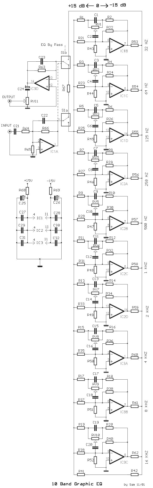
10 Band Graphic Equalizer

The circuit of graphic equalizer, allocates ten adjusting potesometer , that each one from them affects in a predetermined area of frequencies, the central frequency of which abstains a octave (double), from the central frequencies of her neighbouring regions. Each unit has common materials with remainder and it differs only in the capacity of capacitors that constitutes the filter in each unit. When the runner of fader regulation RV1 until RV10, is in the middle then we do not have no intervention of filter above in the signal that passes from in his and gain of particular unit, is one [ X1 ]. On the contrary if the runner is moved to a side of exit, the unit acts as filter of cutting off of area and it degrades the signals of predetermined area of frequencies. On the contrary if it is moved to the side of entry, the rung acts as filter of passage of area, strengthening the signals of predetermined area of frequencies. The quality of all materials should be very good. Specifically potesometer RV1... the 10 and capacitors. If it is intended for stereo use then it will be supposed it is made in two pieces with as much as possible suited the materials, between the channels, so that do not exist differences in the regulation of each band frequencies. Switch S1 isolates the circuit EQ, when him we did not need and it ensures level [ flat ] response in the exit of circuit. The circuit should be connected between preamplifier and in a final power amplifier.

Circuit diagram

Circuit diagram

Part List

  • R1....20= 10Kohms
  • R21....40= 1Mohms
  • R41= 10Kohms
  • R42= 1Kohms
  • R43.....52= 2.2Kohms
  • R53.....62= 47Kohms
  • R63-64-66-67= 47Kohms
  • R65= 10Kohms
  • R68-69= 47 ohms 1/2W
  • RV1....10= 100Kohms lin FADER
  • RV11= 10Kohms log.
  • C1= 180nF polyester
  • C2= 18nF polyester
  • C3= 100nF polyester
  • C4= 10nF polyester
  • C5= 47nF polyester
  • C6= 4.7nF polyester
  • C7= 22nF polyester
  • C8= 2.2nF polyester
  • C9= 12nF polyester
  • C10= 1.2nF polyester
  • C11= 5.6nF polyester
  • C12= 560pF polysterine
  • C13= 2.7nF polyester
  • C14= 270pF polysterine
  • C15= 1.5nF polyester
  • C16= 150pF polysterine
  • C17= 680pF polysterine
  • C18= 68pF polysterine
  • C19= 360pF polysterine
  • C20= 36pF polysterine
  • C21= 4.7uF polyester
  • C22-23= 33pF polysterine
  • C24= 10uF 25V
  • C25-26= 47uF 25V
  • C27...32= 47nF polyester
  • IC1...3= TL074
  • S1= 2X4 SW for stereo

Studiomaster Parametric Equalizer

Schemat, obrazek: Efekty/Equalizer/Studiomaster Parametric Equalizer.gif

Regulator Barwy

Schemat, obrazek: Efekty/Equalizer/Regulator barwy.jpg

Regulation barwy - Laney TL072

Schemat, obrazek: Efekty/Equalizer/Regulacja barwy - Laney TL072.jpg

Orban Associates - 672A

Schemat, obrazek: Efekty/Equalizer/Orban Associates - 672A.JPG

Lampowy Regulator Barwy

Schemat, obrazek: Efekty/Equalizer/Lampowy regulator barwy.jpg

Korg Parametric EQ

Schemat, obrazek: Efekty/Equalizer/Korg  Parametric EQ.gif

Impersonator UEQ375 Univox

Schemat, obrazek: Efekty/Equalizer/Impersonator UEQ375 Univox.gif

Ibanez 7 Band equalizer

 Efekty gitarowe - Equalizer - Ibanez 7 Band equalizer

Equalizer Fuzz

Schemat, obrazek: Efekty/Equalizer/Equalizer Fuzz.gif

Elektor Parametric EQ

Schemat, obrazek: Efekty/Equalizer/Elektor  Parametric EQ.gif


Cpm Affiliation : the cpm advertising network


make cash


Hobby Elektronik Copyright © 2011 -- Template created by Acakadut -- Powered by Firman Wahyudi